Prusa Heated Bed Replacement
During some of the initial calibrations of my Prusa 3d Printer I made the mistake of calibrating the printer while the heated plate was hot. The made it possible for the extruder's tip to create modest gouges into the heated bed of the prusa printer. Normally, this would not have been an issue but as I started to print some of the larger parts for the antenna array I decided that it was time to replace the heated bed. This will be a quick tutorial on how to replace the heated bed of the Prusa.
Ordering Parts
To replace the bed of the 3d printer we are going to need 3 parts. First we will need a new bed, second we will need the coating to go overtop the bed, and third we will need Kapton tape. These can be found through the links below
Removing The Old Bed
Before starting to take the 3d printer apart be sure that the 3d printer is unplugged. Start the process by turning the printer over on its side. From here you will have easy access to the screws holding the heated bed in place. We will be removing those screws but first, note that at the point where the power connects to the heated bed there is a screw. Unscrew this screw so that you can gain access to the solder points of the heated bed. For details see the image below.
.png)
Once the screw holding solder cover down has been removed turn the 3d printer back over. At this point it will be possible to remove the solder cover. As shown in the image below, this will uncover the connections between the board and the controller. In order for the new heated bed to function correctly it is necessary that the two black wires going to the board are disconnected. Note that one of these black wires should have a red stripe, this wire will be connected to the Vcc Pad, the other wire is entirely black and is connected to the ground pad. In addition to these two wires, observe that there is also an LED and a 1KOhm resistor attached to the board. If you do not have replacements for these components they also will need to be removed from the board and attached to the new pad.
.png)
Once the connectors, LED and Resistor of the heated pad have been removed, flip the 3d Printer on its side a second time. At this point we are going to loosen the cable that is used to move the heated bed along the y axis of the 3d printer. This can be done by removing one of the screws securing the stepper motor and twisting the stepper motor to slack the line. See the images below for details.
.png)
Next remove the cable from its connection to the 3d printed bed. To do this just carefully work the cable out of the orange 3d printed holder.
.png)
Once the cable is disconnected we can unscrew the screw connecting the heated bed to the cable holder and the 3d Y axis frame. For details see the image below.
.png)
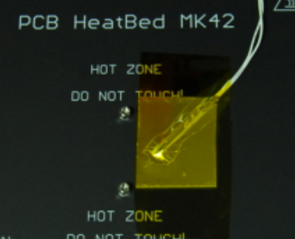
Now we can safely lift the old heated bed off of the 3d printer. Be careful though because there still should be two white wires taped to the old heated bed. These wires are attached to the thermistor of the heated bed. These wires are used to measure the temperature of the heated bed. See the picture for the typical attachment of the thermistor on Prusa heated beds. Remove the thermistor and the tape connected to it. Be sure to note that there is a circle marked on the bottom of the bed designating where the thermistor goes.

Next look at the top of the 3d printed bed, as seen in the picture below there should be screws which can be seen from above but are protected by a clear sheet of PEI. We need to remove these screws and use them for the new printed bed. To do this you will need to peel of the PEI sheet. This may take some force but it does not matter if the PEI sheet is damaged in the process. Once all the screws have been removed we can start the process of attaching the new heated sheet.
.png)
The process of installing the new 3d printed board is largely just reversing the steps above. Start by placing the screws removed in the last step into the new heated bed. The thermistor can then placed on the new bed using Kapton tape. Following this attach the new heated bed to the Y axis frame and also reattached the Y-axis cable holder to the heated bed. Once this is complete replace the Y-axis cable into its holder and replace its tension by re-securing the stepper motor in the correct position. Solder the LED, Resistor, and power cables to the new heated bed, also attach the 3d printed cover for these components. The last step is to attach the PEI sheet to the heated bed. To do this mark out the size of the heated bed onto the PEI sheet and cut it out. With many PEI sheets if you score the surface of the sheet it will break along that score if you bend the material. Another tip is to use the older heated bed to mark out the size of the new bed, as they should be identical sizes. Once this is done each PEI manufacture will have their own instructions for attached the PEI sheet to the heated bed. Typically you attach the PEI sheet while the heated bed is cold. Once the sheet has been pressed down the bed is then heated up to a temperature specified by the manufacturer. This process ensures good adhesion between the PEI sheet and heated bed.